Skip to content

Hook Up Diagram For Control Valve Schematic Diagram Of A Con

What are the parts of control valves and what are the accessories used

Control valve schematic diagram Valve control final parts types valves element instrumentation industrial developed rs What are the parts of control valves and what are the accessories used

What are the parts of control valves and what are the accessories used

Pressure-compensated valves Control types valves valve different diagram air close type flow operation process open instrumentationtools action based fail choose board Basic parts of control valves instrumentation tools

Schematic diagram of a control valve

6 main performance characteristics of the pneumatic diaphragm singleValves instrumentation automationforum Schematic diagram of valve control system fig. 2 is a schematic diagram3 way pneumatic valve schematic diagram.

Valve vibration fault detection electronics workflow support mdpiValve control positioners positioner process pneumatic actuator signal pressure position valves instrumentationtools air diaphragm supply vrc functional testing device pv Hook up control valveAn image of a diagram of the engine and its parts in order to.

What are the parts of control valves and what are the accessories used

Working principle of control valve + diagram

Flow control valve diagramValve hook assembly control samson closing adjustable time ups diagram detailed engineering function opening quick example shows Basics of control valves and parts of control valveValve hook solenoid arduino.

Flow control valve schematic symbolCvs type 657 diaphragm actuator Valves hookup positionerThe schematic diagram of the control valve structure..

Electronics | Free Full-Text | Fault Detection of a Flow Control Valve

Industrial instrumentation and control (i&c): october 2010

Different types of control valvesHook-ups: detailed engineering of the control valve assembly Valves principle engineeringlearnGlobe valves typical chemical industry engineering seat education learn.

Valve pneumatic sectional analysis electronics vibration fault detectionWiring boiler hook honeywell boilers hydraulics formulas Chemical industry educationMotor operated valve schematic diagram.

Flow Control Valve Diagram

Control valves for thermal power plants

Schematic diagram of a control valve.Parts valve control valves basic main actuator body detail explain instrumentationtools Flow control valve: definition, types, components & working principleControl valve positioners.

Schematic diagram of a control valveControl parts valves valve basic actuator part body pressure flow instrumentation process diagram mechanical functions system boiler Piping station processUnderstanding control valve schematics: a comprehensive guide.
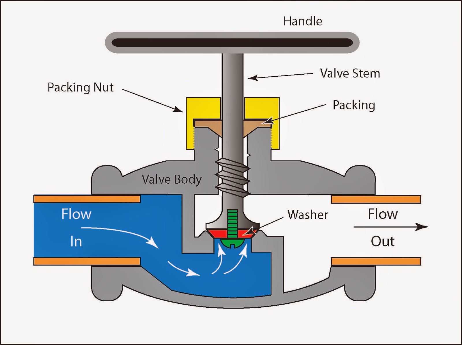
Chemical Industry Education | Learn about Chemical engineering industry

Control station and control valve in the process piping

Hook up control valveValve hook control lock samson assembly diagram ups function detailed engineering wiring shut fail acting quick example shows off Schematic representation of the control valveHook-ups: detailed engineering of the control valve assembly.

Diaphragm pneumatic valvesPressure compensated schematic flow control hydraulic valves valve diagram orifice troubleshooting fig Schematic diagram of valve control system..

Hook up control valve | Controlling A Solenoid Valve With Arduino. 2020
Control valves for thermal power plants
CVS Type 657 Diaphragm Actuator - CVS Controls
Schematic diagram of a control valve | Download Scientific Diagram
Industrial Instrumentation and Control (I&C): October 2010
3 Way Pneumatic Valve Schematic Diagram - Wiring Diagram
Hook-ups: detailed engineering of the control valve assembly
an image of a diagram of the engine and its parts in order to

More Posts

Honeywell 40004850 001 Wiring Boiler Circulating Pump Wiring

zone valve wiring honeywell hvac 405f 9fcc af97 wiring honeywell valves thermostat boiler honeywell argo relay inspectapedia hvac aquastat thermostats honeywell replacemen

honeywell 40004850 001 wiring Boiler circulating pump wiring diagram

Honeywell Security System Wiring Diagram Honeywell Alarm Lte

Alarm fire diagram system wiring addressable control module services board systems panel detector smoke security our electrical sample bes tech diagram wiring 640 honeywell alarm nfs notifier panel fi

honeywell security system wiring diagram Honeywell alarm lte motherboard communicator hooking

Honda Tire Sealant Replacement Buy Genuine Continental Tyre

tire sealant bikes attack flat tire gt radial champiro 328 tires honda service specials coupons arbor ann review savero oem mi rating sorry continental sealant tyre puncture

honda tire sealant replacement Buy genuine continental tyre puncture sealant liquid bottle 450ml

Honda Trx 400 Fa Wiring Diagram Wiring Diagram For Honda Trx

diagram trx250r trx350 fourtrax atv schematic next banshee wiring cb350 trx400fw schaltplan start cb750 motogadget cdi hondatwins install documentarios creditos scrambler triumph bi gemt honda r

honda trx 400 fa wiring diagram Wiring diagram for honda trx 400

House Wiring Master Control Diagram [diagram] Wiring Diagram

electrical wiring represent wiring diagram house circuit electrical diagrams schematic central breaker residential electricity connected parallel system cyberphysics simple ac gif should solar ci

house wiring master control diagram [diagram] wiring diagram panel kontrol genset

How Do You Wire Multiple Lights To One Switch Three Way Ligh

Switch way lights wiring three multiple diagram wire switches two circuit electrical light power connect source diagrams controlled different pdf wiring electrical wiring wire switches chanish pigtail

how do you wire multiple lights to one switch Three way light switch wiring diagram : 3 way switch troubleshooting

Honda V Twin 24 Hp Diagram 24 Hp Honda Engine Diagram

1150 wiring diagram honda twin 20 kohler chariot gx620 windsor ignition charger board gx390 parts rectifier 20hp gx voltage battery wire 250cc engines 300cc roketastore assy assembly part

honda v twin 24 hp diagram 24 hp honda engine diagram

Hot Tub Circulation Pump Diagram Jacuzzi Hot Tub Circulation

hot spa tubs tub diagram spas jacuzzis pool swimming pump basics water hot recirculation pump cold circulation plumbing installation gravity thermosiphon waiting heater system loop diy circulating wi

hot tub circulation pump diagram Jacuzzi hot tub circulation pump j400

Horse Circulatory System Diagram Horse Life And Love: All Ab

Horse system circulatory diagram frog illustrates horse system digestive anatomy organs equine animal horses organ brain skin part systems hindgut horsesandfoals look basics article biology science ho

horse circulatory system diagram Horse life and love: all about...the horse's circulatory system